Drake
L-4B
Drake
L-4B__________
Drake
L-4B
__________

There is nothing quite as impressive to visitors to one's shack (radio operators and laymen alike), than a final amplifier with a big glass tube glowing in all its warm glory...to say nothing of the additional S-units on the air! With ceramic encased power tubes ala 3CXxxxx or transistors, how is one to know there's even anything going on in there? With this in mind, I had slowly been collecting components for the construction of a real "Big-Rig", built around the venerable Eimac 4-1000A. Well ...things change ...and opportunities arise ...so taking advantage of one of these opportunities, I purchased the clean, used Drake L-4B seen above. The L-4B is somewhat smaller than a "4 by1" amp would be, but none the less still pretty impressive, using two 3-500Zs [Ref 1] in grounded grid.
The components originally collected for the 4-1000A rig are available and will be liquidated, and are available. See For Sale Items!

Smaller than a 4 by 1, but still impressive, no? (Just about
life-size!)
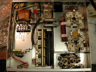
Initial Inspection Upon receipt and initial inspection, the RF deck was in generally very good shape, needing only some minor repairs and preventative maintenance...aged weather-stripping foam which seals the bottom cover to the chassis needed to be replaced, surprisingly, no force limiting was used on the hardware of the ceramic tube sockets for the 3-500s, this undoubtedly contributed to one cracking, and the plastic strips holding the filament choke in place had hardened and cracked - all minor items really.
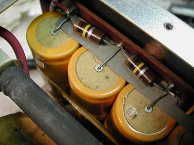
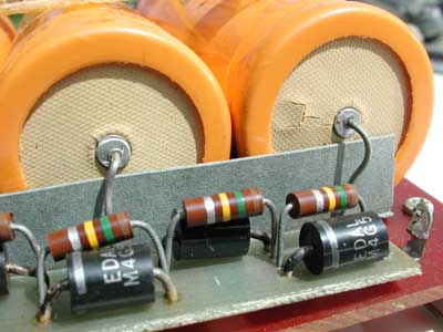
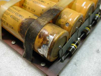
But the high voltage electrolytic caps of the power supply sported the original 7552 datecodes, and were looking pretty scary, showing definite signs of age and impending (maybe) explosive incontinence (see pix), so rather than risk their catastrophic failure and possible further damage, I decided to replace these before applying power. As axial lead caps in the required ratings are no longer available, I used radial lead types held to the boards by RTV (physically a lot smaller, but even with a bit more capacitance, at 220μF, compared to the oe 200μF!).
A more careful examination of the tuning capacitor revealed evidence in several places, of slight plate melting and decrease of plate spacing (due to arcing from operating into a poor match, or maybe "high power tuning"?...see below)..I was not happy to see this, but it was minor...I decided to grind the plates back down to their original thickness to at least get back to the original voltage rating of the cap.
Power Supply
|
|
|
|
|
|
Also, I wasn't there to hear or see the lightning strike which must have occurred in this PS when R12 blew (the series, 0.82Ω protective resistor in line with the high voltage output of the power supply), but from the description of L7 operator N9AUJ, and the forensic evidence left behind, this PS must have experienced the same!
An excerpt from a response post: http://lists.contesting.com/archives/html/Amps/2003-11/msg00181.html
[How about meter
readings? When the close the key line with no RF drive, are you
still getting normal zero signal anode current (~140mA). How about
grid current?
BTW, you are correct the 0.82 ohm resistor is supposed
to be a high voltage fuse. A number of amplifier gurus
recommend that this be replaced with a high voltage globar type glitch
resistor (10 to 30 ohms). The idea is to limit the instantaneous anode
current to a reasonable value in the case that a high voltage fault occurs
in the RF deck. The 0.82 ohm resistor "fuse" may not blow fast enough or
it may arc across. In either case, this will allow for a very high
instantaneous dump current when the capacitor bank dumps its charge through
the fault, which in turn can damage the
tubes.]
In corresponding with N9AUJ, he apparently had not grasped the importance of tuning up at low power only. I intend not to learn in the same way!
-----------------------------------------------
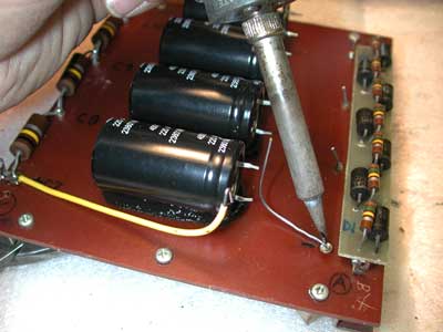
Upgraded Power Supply

Upgraded Power Supply, showing replacement capacitors,
and a sheet of Teflon added to make an R12 blast containment area!!
-----------------------------------------------
Additional:
Doing some further researching to find if there were any other areas of
weakness or operational upgrades, I learned of the following:
Power switch failures due to inrush current.
"Soft-starting" the tube filaments to limit the cold inrush current.
Interfacing to Icom IC756 Exciter
The original equipment power switch is overworked by inrush current . Some owners also recommend the installation of "soft-start" circuits to limit inrush currents to the filaments. [Ref 2] After discussing this at length with N1KW, I believe these are two related but really separate issues, and will handle them as such. There is little doubt that the power switch can stand improvement (especially a problem with double the currents encountered in 115VAC operation), but Bob made clear to me that directly heated filament tubes such as the 3-500zs are perfectly capable of, and even fully intended for instant heating!
Seen from the front panel, the Power and SSB - CW/Tune switches look like two full-size, common rocker switch of days of old. A closer look behind the front panel reveals that they are actually one full size switch with two rockers, each using half of the switch...cost reduction ala 1970? Separate, full-size switches would have allowed the power switch to share switching duty between two contacts, but unfortunately, this is not possible here...I'm sure also, that those custom switches are not available, and even if they were, a replacement switch would be similarly overworked. An upgrade is clearly called for.
I have mixed feelings about hard-starting the filaments (indeed, the tube data sheet suggests limiting the inrush current to 2X the nominal value). From the Eimac data sheet "For best tube life, the inrush current to the filament should be limited to two times normal current during turn-on. This will minimize thermal stress on the thoriated-tungsten filament wire, which can cause internal tube geometry changes with repeated cycling." We'll see...
In view of this, my present decision was to install a power relay, slaved to the existing power switch, and to not install any soft-start feature at the present.
RF Deck
Under-chassis view of the clean RF deck. Aging and cracked filament
choke holders
have been replaced, fibre washers have been installed under all ceramic
socket bolts.
Plate tuning capacitor repair.
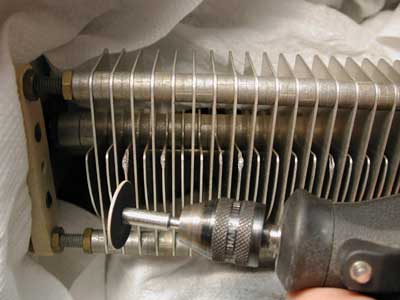
Plate tuning cap with aluminum globs, ready for some minor dentistry.
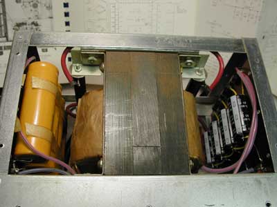
Power Switch Upgrade.
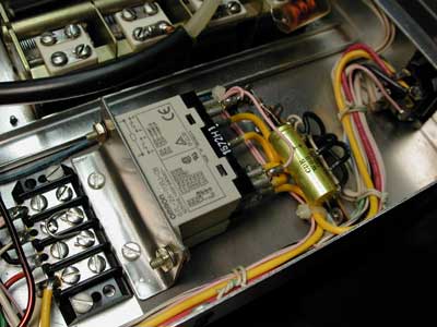
Power Relay installed
An Omron (PN G7L-2A-TUBJ-CB) 220VAC coil type relay with four 25Amp rated working contacts, slaved off the power switch will now handle the power switching (see wiring diagram). Luckily there is adequate room to mount it in a perfectly logical place right next to the filament transformer, using the existing hardware of the plate tuning coilform. Handy! Mounted on a custom little 304SS bracket (nothin' but the best for the girls I go with!) ...and no new holes required !

Partial RF deck wiring
diagram.
-----------------------------------------------
Power Up...yeah baby!
1800Volts on plate in CW/Tune position, 2550V in SSB position.
1200Watts out indicated. The dummy load was toasty!
More coming...stay tuned!
Internal transistorized keying upgrade.
Initial power up tests were performed using a test clip to key the amp into transmit mode. Measurements on the keying input (open circuit voltage: 30V, short circuit current: 50mA), confirmed that an interface circuit would be required, as the current is (well) within the ratings of the Icom, but the voltage is not. N1KW at Redstone Consulting suggested the following circuit, using two 2N3440 (300V rated, TO5 case) transistors, which limits the voltage and current at the connector to .6V, 3mA respectively.
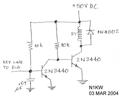
A new RCA jack was located next to, and paralleled with the original Key connector (yes, I drilled two new holes into the panel!). All new components were installed on an adjacent terminal strip. A free wheeling diode was added across the key relay to snub the turn-off spike and keep the transistor from going to the happy hunting ground. This upgrade makes the keying input fully compatible with the Icom 756, and any other exciter out there, including the connectors...nice! A standard RCA to RCA cable can now be used to link the exciter to the amp. The circuit worked first time...every time!
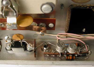
Keying upgrade
interface in
place on rear panel. Also visible at top center is one of
the homemade
fiber washers which were installed under all ceramic socket bolts.
----------------------------------------------------------------------------------------------
A coax fed 20m dipole was quickly constructed and raised, as a high power rated antenna tuner was not yet available to put the power to the 80m Zep. Initially, signal reports using this antenna with low power alone were (surprisingly) 2-3 S units improved over the 80m antenna (with 20m elements)!! Putting full power onto the antenna yielded the best signal reports ever, by far, from "9Land". I will operate using the 20m coax fed antenna initially, but do intend to construct a tuner (a link coupled tuner design for open feedline of course!), which will allow me to load up the 80m Zep on all bands. ...I also need to do some antenna improvements to keep from lighting up the supporting trees....and I certainly don't want to operate a "full gallon" without first upgrading my license to Extra class....
-------------------------------------------------
References:
Ref 1. 3-500z data sheet: http://home.c2i.net/clank/ham/pa/3-500z.html
Ref 2. Inrush current study: http://www.kristronic.com/lx2kl/
----------------------------------------------------------------------------------------------
----------------------------------------------------------------------------------------------
Additional Drake L-4B pages of interest that I ran across while surfing:
Cooling on 50 Hz: http://www.kristronic.com/lx2kl/drake_L-4B.htm
Drake Links page: http://www.geocities.com/maxmartin3/dlinks.html
Drake page: http://www.qsl.net/n9bor/drake.htm
Drake Mods including Soft Keying Module, 0.82 ohm resistors, Soft Start Module: http://www.harbachelectronics.com/reference/harpg4cart.htm
How a tube converts DC to RF energy: http://www.w8ji.com/Vacuum_tube_amps.htm
Amplification principles: http://www.astrosurf.com/lombry/qsl-amplifier-principle4.htm good additional links!
How a vacuum tube works: http://www.svetlana.com/docs/tubeworks.html
pdf of QST article: http://www.dproducts.be/drake_Museum/qst_12_1969.htm
http://www.wb4hfn.com/DrakeArticles/TechTips/DrakeResources.htm
Restoration Paints: http://www.nctotalelectronics.com/
RF Parts comparison of 3-500z tubes: http://www.rfparts.com/tubecomp.html
3-500z Data sheet: http://home.c2i.net/clank/ham/pa/3-500z.html
Interfacing an L-4B to an IC756: http://www.qsl.net/kk5dr/IcomKeyInterface.html
Increasing Amplifier Relay Speed Article by Bob Wolbert, K6XX http://www.k6xx.com/radio/fastrely.html