
Service of Grundig YB-400
R.Kwas KA1-RBP Aug/2016
External Power Fault Condition
Part 2
Service
of SN...981
-------------------------------
The first service to apply Deoxit D5 to the Volume Control of SN 271981 to cure and mitigate terrible scratchiness lasted for along time...better than ten years! I'd like to see simple tuna cleaner do that! A second YB was procured in the interim: SN 024934 This page will document service to both.
Service to SN...934 first. [Link to Service of YB-400 SN...981]
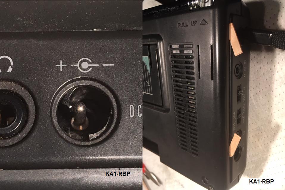
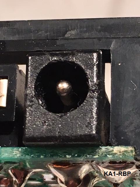
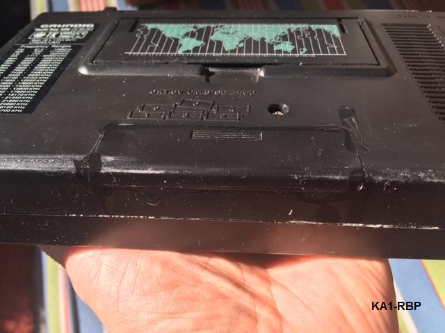
DC Power Jack worked when last tested, but has some issues...the center pin appears bent...and there are bits of plastic broken and out of place...damage possibly from a sideways tug on the power cable while plugged in (see: Additional Information, operation from external DC power). This will be inspected closer when radio is apart and repaired depending on evaluation of what is found. Radio could also use a good cleaning which will be easier while removed from case. Finally, Volume, and all Slideswitch Controls will receive a preventative Deoxit D5 treatment.
Disassembling the YB-400:
Note: No special tools beyond normal electronic bench tools were necessary. Particular or special chemicals used were: Isopropyl alcohol, Deoxit D5, Superlube, Triflow, Cyano-Acrylate (CA) glue, Anti-Corrosive Zinc Paste. See Reference Information for links on these. No special Anti-Static handling practices were observed during this work, as no components were handled out of circuit and humidity at the workbench was relatively high.
Convention:
General references will be in lower case type. Reference to specific parts
and components of the Radio itself will be in upper case type.
Notice: This record and comments have been prepared based on
my own experience, and with the utmost care, but must be used by others in
conjunction with judgment, and normal safe electronics service bench practices.
You alone are in charge of your fingers!
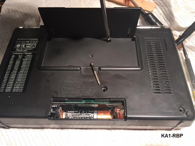
Batteries will first need to be removed...and when the Battery compartment door
is removed, the first issue is revealed, a leaking Battery (although with 2017
date codes!)...thankfully, there are no metal parts anywhere near the caustic
leakage, to damage, so damage seems confined to Battery itself. All
Batteries are removed (and found to be well discharged at around 1.0 Volts*),
and the accessible areas of Battery compartment get an initial cleaning with a
cotton swap and isopropyl alcohol.
* YB-400 Current Consumption measured: XXXmA standby, XXXmA when ON, at medium volume...that's why operating it on the DC power jack is preferred whenever possible, saving the Batteries for portable operation. As excerpt of schematic below in Additional Information shows, the Batteries are disconnected (or are supposed to be!) when DC Plug is engaged, so no recharging of Batteries will take place.
4 (Philips #1) screws total, marked in Red, secure the case halves together...one is located under the hinged prop.
Case screws are removed. A bit of gentle force is required to help separate the case halves. A couple of pieces of wooden coffee stirrers are used for this...these are just the right thickness, and soft so wont damage the plastic at points of contact.
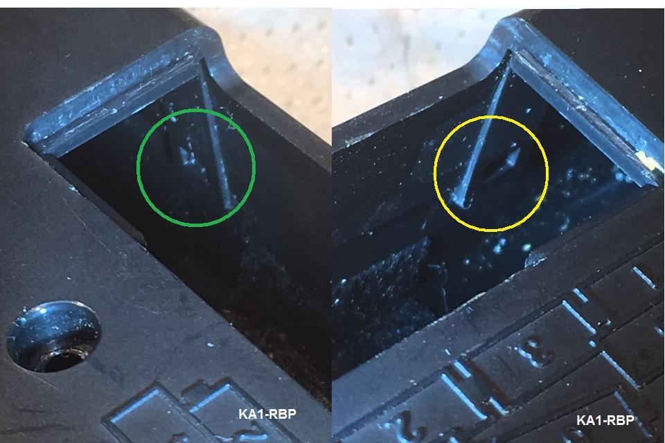
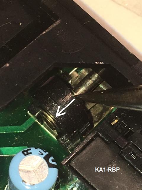
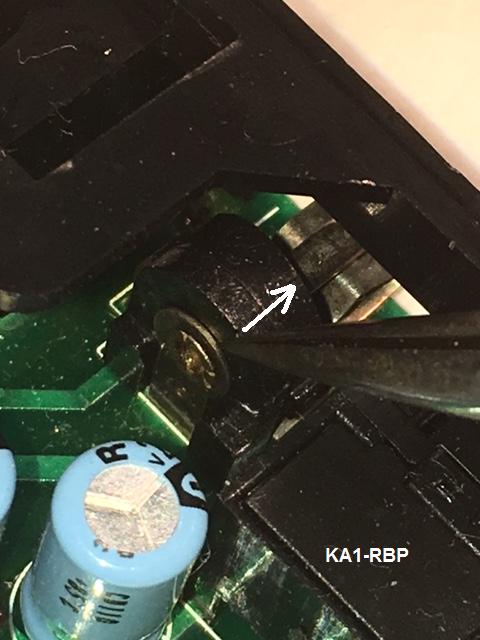
Two catches, hidden in the battery compartment must be gently defeated...CAUTION: Simply levering at the cases will likely break these catches! Don't Do It! The catch in Green is shown in the normal position, in Yellow, released.
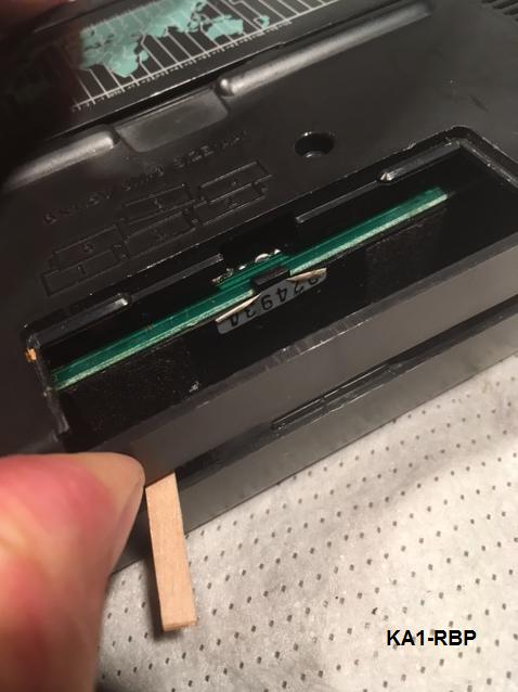
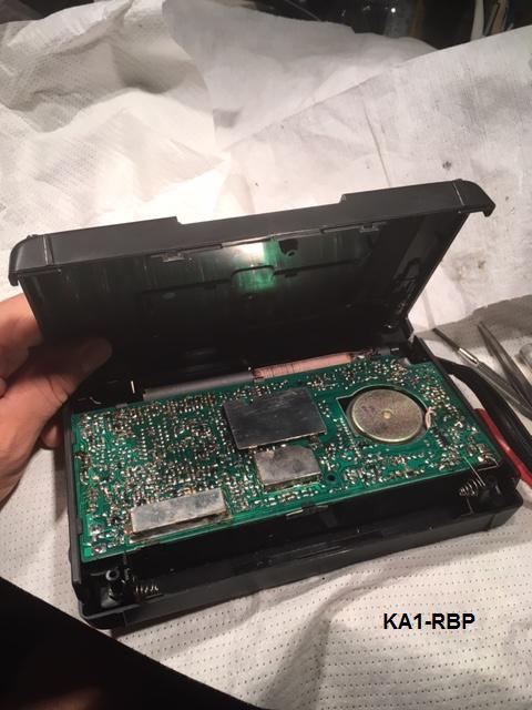
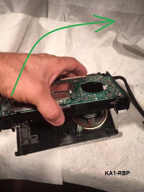
To keep the first released catch from re-engaging while manipulating to get the second one to release (to prevent one step forward, one step back!), the wooden coffee stirrer trick is used again. Once the second catch releases with possibly an almost alarming SNAP(!), the back case half can be gently folded up like opening a book, hinged at the antenna side, until two additional catches at that side also release.
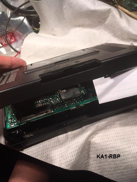
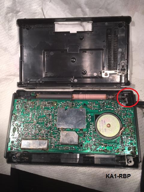
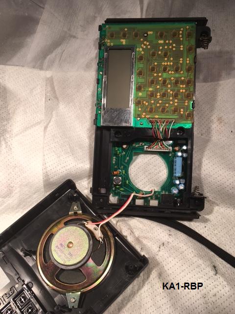
The innards are revealed...a quality G10 PCB with Surface Mounted Devices (SMD), several shielding enclosures, typical ferrite rod internal AM antenna, and a decent Speaker. Nice design and clean implementation! Thankfully, no additional damage from the leaking Battery is evident.
A single screw, located in the upper right corner, marked in Red, which secures the PCB assembly into the front case half, is removed.
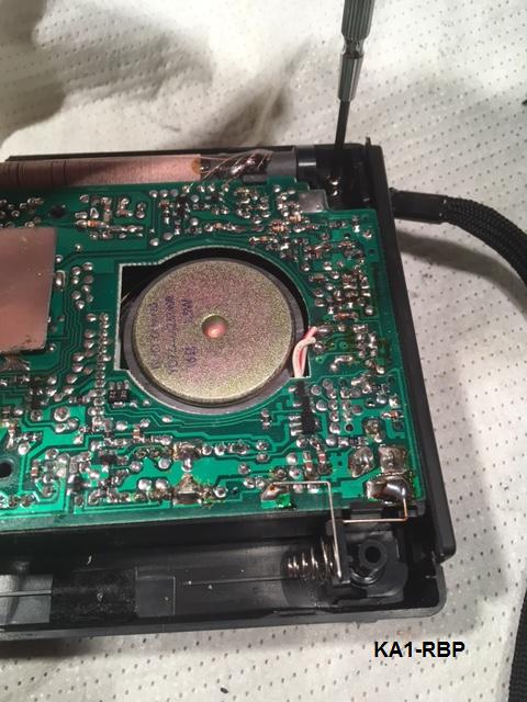
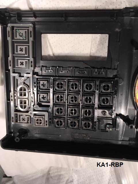
Removal of the screw allows lifting of the internal assembly from the front case....gently!...speaker wires still connect the two! There's lots of dirt on the external side of membrane for switches, and a peek under the membrane shows gold plated switch contacts. Again, clean design, construction, and high quality are in evidence throughout.
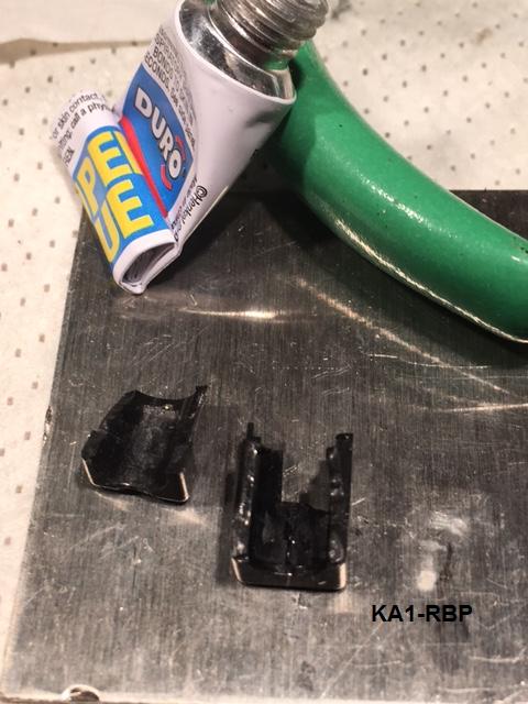
Assembly endplates at either end pop off locating pegs easily and little caps which bring slideswitches out beyond the endaps are simply lifted off slideswitch actuators. Everything get a good cleaning with alcohol wetted cotton swabs, then placed in plastic bags for dust-free, safekeeping. Fractured part of Power Jack falls away Red as well as one of the slideswitch actuators Green.
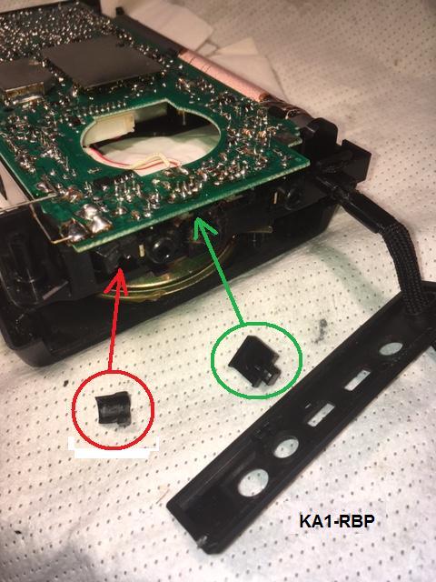
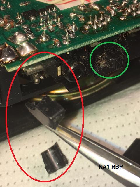
A total of three fractured pieces of the power socket are removed at Red, one of the slideswitch actuators is shown in place...along with lots of dust...everything gets a good cleaning as it comes apart.
Speaker wires are desoldered to allow separating the internal assembly from front case.
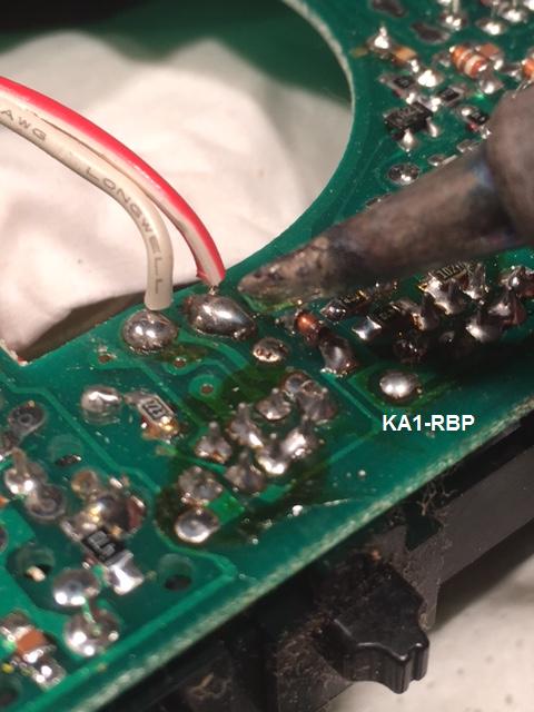
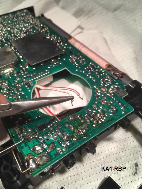
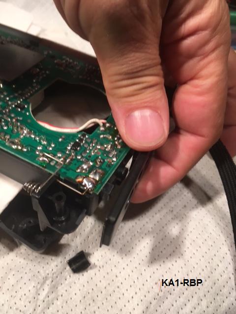
The Power Jack is closely inspected...without the broken supporting plastic housing in place, a fair amount of movement is possible, back and forth in the axis of force that would be applied when the power plug in inserted. Solder joints are fine, and plastic housing damage is the only damage apparent.
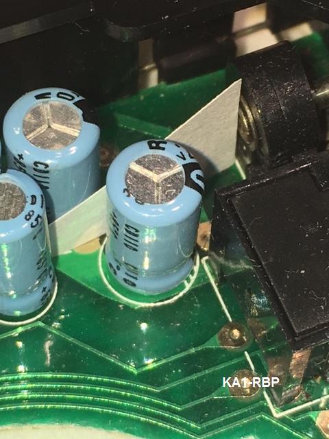
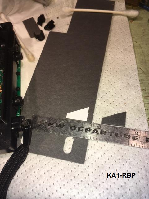
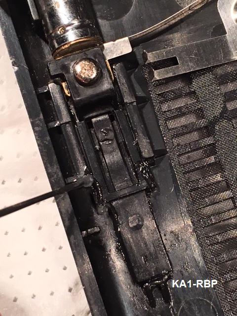
I decide the repair will consist of gluing the plastic housing together with CA, replacing it, and to install a supporting gusset behind the jack to give additional support against the plug insertion force. There is room for this, and test fittings show it can be nicely fit between several capacitor cans there. The gusset is designed of paper, and will actually be made and installed of fiber reinforced resin board (Trade name: Fishpaper).
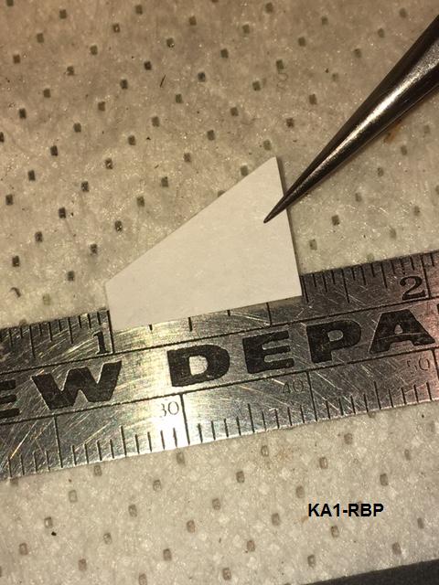
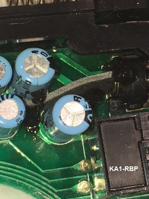
Once Gusset design is finalized, it is cut from the stiff Fishpaper material, positioned giving power socket a little preload, and glued into place with RTV. I prefer RTV as it has the option of being easily cut away and removed in the future, unlike epoxy or more permanent adhesives...the dabs are as neat as was possible given the tight quarters.
Next, the broken parts of the Power Socket are reunified with CA glue, and replaced and glued back into their original position, including to the PCB. Once everything is back in place, now supported by the gusset, alignment looks good.
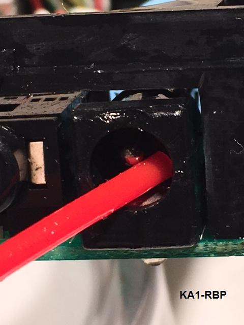
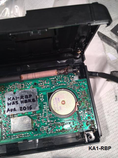
The Radio is prepared for reassembly...and all controls and jacks, including the newly repaired DC Power Jack are treated with Deoxit D5, the antenna position sliding mechanism (plastic on plastic) is lubricated with Superlube. After screw is removed and interfacing surface of antenna connection is cleaned, a dab of Anti-Corrosive Zinc Paste is applied before screw is replaced.
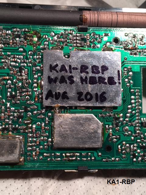
A final cleaning and dedusting is performed, and internal autograph is left recording the service date.
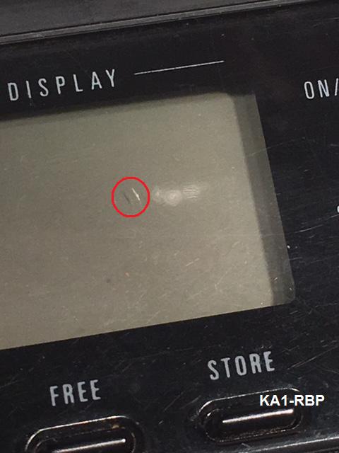
Radio is prepared for reassembly...display is carefully checked for and cleared of inclusions like the one circled...it would be pretty annoying to have to stare at that piece of FOD! Ideally, the service bench should be in a clean-room...having a mini-vacuum available is a good second choice. Internal assembly is secured to front case with single (short) screw. A miniscule dab of Superlube on the screw threads, and using the technique of turning in the reverse direction until a pop is felt and heard, to assure going into the existing thread is used. Only after display passes the Perfectly-Clean-Test, rear case half is located and snapped into place, and secured with the 4 (long, also lubricated) screws.
After reassembly, Radio is powered up with fresh Batteries, and functionally checked. I didn't try it on the Ext. DC input (I'm confident it will work since it was not an electrical problem). A few drops of Tri-Flow lube on a wiping cloth is used to lube the extended antenna. This keeps force to compress it at a minimum preventing possible kinking.
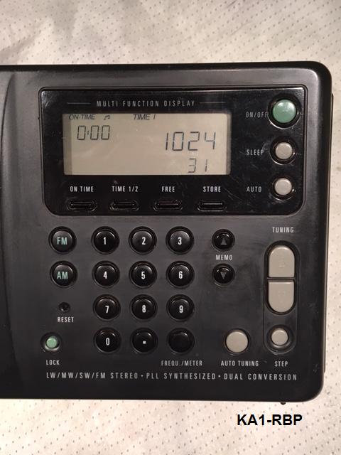
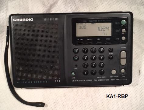
YB-400, ready for return to service:
I expect service to the second radio SN ...981 will go similarly...if there are any differences or points of note, I will add them here.
------------------------------
Deoxit D5: http://store.caig.com/s.nl/sc.2/category.188/.f
Superlube: http://www.super-lube.com/synthetic-multipurpose-grease-ezp-49.html
Anti-Corrosive Zinc Paste (my generic term for zinc dust filled grease, like Burndy's Penetrox A): https://objects.eanixter.com/PD372804.PDF http://ecat.burndy.com/Comergent/burndy/cat/602945
Tri-Flow: http://www.triflowlubricants.com/product/superior-lubricant-drip-bottle
------------------------------
Operating the YB-400 from external DC power.
Why are there so many connector sizes for DC coaxial connectors? Is that really necessary? When there is a slow day around the engineering department, do they design a new one to add?
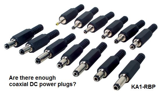
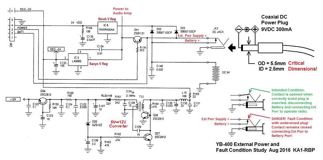
* I've found it to be good practice to operate the YB on line power with a 9VDC supply. The radio is a reasonable consumer of batteries, when volume is at a modest level, but anything to save the Batteries for portable operation is a good thing. "Wall-warts" were/are available, and the correct dimensions for the coaxial power connector are 5.5mm OD and 2.1mm ID with outer ring polarity positive. Simply using one of the correct output and polarity is not enough! Dimensions of coaxial power plug are critical to prevent fault condition leading to Battery leakage! See also CAUTION Below!
External Power Fault Condition:
Excerpt from the YB-400 Manual:
"Output of 9 volts DC, negative polarity (tip negative); 300 millampere current capability; coaxial plug outer
diameter of 5.5 millimeter, inner diameter of 2.1 millimeter. NOTE: Using a plug tip diameter smaller than
5.5 millimeter may not cut off voltage to the battery compartment and can cause batteries to overheat, leak
and destroy circuits. This will void the warranty. "
Good YB Information: http://www.knietzsch.com/amateur_radio/ham_yb400.htm
--------------
Part 2
[Update April 2017] It's time to service SN...981 again! It's been well over 15 years that the first application of Deoxit D5 cured and prevented the return of a scratchy volume control, thanks to the effectiveness of the product...but the scratchiness has now returned...and since I now use the radio daily, the scratchiness bothers me daily...so it's time for the radio to spend some time on the service bench!
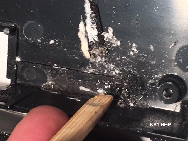
I had put new alkaline Batteries into it to prevent electronic Alzheimer's, yet kept it under continuous wall-wart power, and sure enough, again there were signs of Battery leakage...so much in fact, that the dried white dusty byproduct was preventing the Battery compartment from being slid open...oh dear!...did the "External Power Fault Condition" occur...? ...or did the batteries just leak? I expect its the former. On closer inspection, the white crystalline material can even be seen at the case seam...
Not wanting to damage the Battery Comp Door, I applied several drops of Tri-Flow oil onto the dry white dust in the seam, expecting it to be wicked in to soften the crystalline mass and allow opening. After a few hours of soaking, the Tri-Flow had the desired effect and Bat Comp Door was able to be slid open with little difficulty...I feared what I might find inside...yep, my fears are realized!...all Batteries (Duracell, Dated 2024!) had leaked again...damn, I am not happy about this!...I'll have to perform some tests to see if the External supply was somehow inadvertently connected to the Batteries (this should not occur if an external power connector of the correct dimensions is used, see External Power Fault Condition above!) Batteries are all semi-locked into place by that white leakage by-product and had to be mechanically coaxed out individually...but I was able to do this also without collateral damage. Nastiness appears to be confined to Battery Compartment, but we'll see definitely only after a full damage internal inspection.
Only after removal of the nasty Batteries would I be able to see about opening the case. The gentle pressure-and-coffee-stirrer-technique as shown above, was used again, to separate the case halves without damaging the latches...with success!
Clean-up of Bat Comp with Isopropyl Alcohol and cotton swabs. Iso-Alc works well to soften the crystalline leakage by-products (extremely caustic Potassium Hydroxide according to a popular reference cited below) and allow their complete removal, without attacking any of the case plastic. A chop stick whittled into a flat, soft, scrapper helps.
Both case halves were cleaned well of corrosive battery products, then the Deoxit D5 application to (all) controls, particularly the Volume Control, and also Battery contact springs for protection.
I am convinced that Battery leakage was again caused by inadvertent connection (aka: SHORT! ) of wall-wart power to the Batteries, tying the two power sources together, resulting in reverse current (unallowed recharging!) of the alkaline Batteries. I am considering adding an isolation diode as shown below, to absolutely and once and for all, prevent such a condition from reoccurring. ...and since the forward drop on any isolation diode would decrease the effective Battery voltage to operate the Radio, it clearly should be a Schottky diode with low VForward to minimize the effect. I have selected a 1N5817 (0.32VF at 0.100AF) for the job. Space is tight, so an SMD package will be used once I determine the electrically and strategically correct location. Watch this space for details once the design modification is checked and proven.
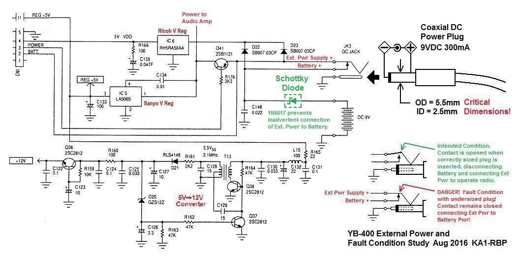
Electronic prevention of leaking Batteries due to
External Power Fault Condition in
the YB-400.
Finally, the case halves were cleaned again, radio is reassembled and returned to service.
------------------------------
PLACEHOLDER FOR UPDATE AFTER ADDING THE SCHOTTKY ISOLATION DIODE:
------------------------------
Reference Information:
Link to Yahoo Group discussing Y-B400 issues: https://groups.google.com/forum/#!topic/rec.radio.shortwave/DRFlNOj9zBs
...from there, Battery current is stated as 90mA...it was not mentioned under what operating conditions, I expect it would be highly dependent on volume level. This value has not been confirmed by me.
https://en.wikipedia.org/wiki/Rechargeable_alkaline_battery
https://www.duracell.com/en-us/help/faq/can-alkaline-batteries-be-recharged
Link to 1N5817 Data: http://www.onsemi.com/pub/Collateral/1N5817-D.PDF
------------------------------
External material sources are attributed. Otherwise, this information is Copyright © 2016-2017. Ronald Kwas, KA1-RBP. The information presented comes from my own experience and carefully considered opinion, and can be used (or not!), or ridiculed and laughed at, at the readers discretion, and jeopardy. As with any recipe, your results may vary, and you are, and will always be, in charge of your own knuckles, and future!
You are welcome to use the information here in good health, and for your own non-commercial purposes, but if you reprint or otherwise republish this article or diagrams, you must give credit to the author and to this site as the source. If you don’t, you’re just a lazy, scum sucking plagiarist, and the Boston Globe wants you! As always, if you can supply corrections, or additional objective information or experience, I will always consider it, and consider working it in...along with likely the odd metaphor and probably wise-a** comment.